>> RS232-TTL UART COMMUNICATION ON ARDUINO USING MAX232
One for those difficult to find solution with explanation with
example code - so here it is!
When interfacing with third party components; sometimes it is not enough
to simply detect digital output values as I have
covered previously -
in many cases; there may be a RS232 or RS485 interface exposed to cater for
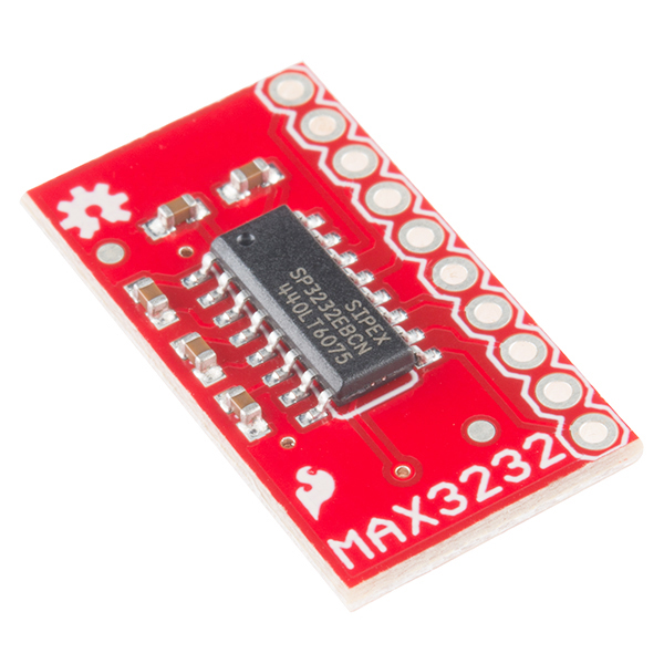
hardware configuration or calibration. This is where a MAX232 SOIC
can be utilized, such as the
MAX3232 breakout
board from Sparkfun to talk RS232 over TTL.
Most micro-controllers have built in TTL (transistor-transistor logic) based
UARTs (universal asynchronous receiver/transmitter) that allow communication
one bit at a time at a specific data (baud) rate; the signal levels
alternate between 0V and Vcc (often 3.3V or 5V) where HIGH is 1,
and LO is 0 often over the RX/TX PINs; these
by default get mapped to USB for Serial Debugging.
A much older telecommunication standard, RS232 (recommended standard 232)
is utilized a lot that allow communication one bit at a time at a specific
data (baud) rate yet also allow for parity and/or stop bits. At hardware
level; things are different - namely that HIGH is between -3V and
-25V and LOW is between +3 and +25V. -25V to +25V doesn't map
nicely to 0V to 5V.
This is where the MAX232 comes into play - it acts as a translator of
RS232 to TTL signals.
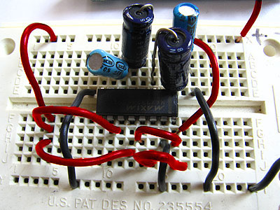
You could wire one of these up yourself; but the capacitors are typically
huge and it'll look like this:
Thankfully; the guys at Sparkfun have made this a nice little neat package:
(MAX3232 breakout).
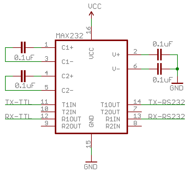
Once you have the MAX3232 breakout; the next stage is to wire it up to your
Arduino and third party components. The MAX3232 will be powered by 3.3V
and GND from the Arduino and the RX and TX PINS
connected to the T1-in and R1-out PINS. The external
component should have GND wired to its GND and the
RX and TX PINS be connected to T1-out and
R1-in respectively.
Something like this:
       12V ----------------------------------------- VIN
       GND ----+------------------------------------ GND
               |                              +----- RX
               | +-------------------- RX     |  +-- TX
               | | +------------------ TX     |  |
               | | | [ R2o     ] +---- GND    |  |
               | | +-[ R1o  M  ] | +-- 3.3V   |  |
               | |   [ T2i  A  ] | |          |  |
               | +---[ T1i  X  ] | |          |  |
               +-----[ GND  3  ]-+ |          |  |
                     [ 3.3V 2  ]---+          |  |
                     [ R2i  3  ]              |  |
                 +---[ R1i  2  ]              |  |
                 |   [ T2o     ]              |  |
                 | +-[ T1o     ]              |  |
                 | |                          |  |
                 | +--------------------------+  |
                 +-------------------------------+
Now; time to test - here is the basics of an Arduino sketch:
#define rxPin 10
#define txPin 11
SoftwareSerial mySerial(rxPin, txPin);

void setup()
{
  // hardware serial
  Serial.begin(9600);
  while (!Serial) ;

  // software serial
  pinMode(rxPin, INPUT);
  pinMode(txPin, OUTPUT);
  mySerial.begin(9600);
}
Using the
SoftwareSerial
library, I was able to setup a bridge between the Serial Monitor of my
Arduino IDE and the RS232 communications port on the third party hardware.
I just happen to have a
Driving Behaviour Monitor
from Hummingbird Electronics lying around so I put this to the test -
trying to send some known commands to the unit and print the results
on the serial monitor.
Hardware Serial: 9600 8N1 (USB)
-- Serial Monitor
Hardware Serial: 9600 8N1 (RS232)
-- Hummingbird Driver Behaviour Monitor

send (HEX): 24 53 54 5A 2A 0D 0A
send (ASC): $STZ*
recv (HEX): 24 43 61 6C 69 62 72 61 74 65 64 20 0D 0A
recv (ASC): $Calibrated ..

send (HEX): 24 53 43 43 2A 0D 0A
send (ASC): $SCC*
recv (HEX): 21 85 C9 A1 81 41 63 63 65 6C 65 72 61 74 69 6F
            6E 20 53 65 74 74 69 6E 67 73 3A 20 30 2E 33 30
            47 20 66 6F 72 20 31 2E 30 30 73 65 63 20 0D 0A
recv (ASC): !....Acceleration Settings: 0.30G for 1.00sec ..
Immediately; it is obvious that communication is functioning - as the unit
is returning data and confirmation messages over serial when it
responds to some known commands that I have issued. A simple
serial communication bridge sketch can be downloaded below.
![[Valid RSS]](valid-rss-rogers.png "Validate my RSS feed")